Multi-VLAN Segmentation with Inter-VLAN Routing
Overview
Simulate a multi-department office with separate VLANs, I created a diagram with 6 PCs connected to one switch and router.
| Skills Demonstrated |
|---|
| Creating and assigning VLANs for department-based segmentation |
| Calculating and applying subnetting for scalable IP allocation |
| Configuring access ports for VLAN membership on a switch |
| Using straight-through cabling to connect endpoint devices |
| Implementing inter-VLAN routing using separate router interfaces per VLAN |
| Assigning gateway IP addresses based on subnet design |
| Verifying VLAN-to-VLAN communication using ping tests |
| Using CLI commands for hostname config, password hardening, and interface setup |
| Interpreting router and switch output to validate configuration |
| Tools Used |
|---|
| Cisco Packet Tracer |
| Switch Configuration CLI |
| Router Configuration CLI |
| Straight-through Ethernet Cables |
| PC Static IP Settings Panel |
| Command Line Tools (ping, show vlan brief, show ip interface brief) |
1. Network Topology
I separated 6 PCs into 3 VLANs per department:
- VLAN10: Sales
- VLAN20: HR
- VLAN30: Engineering

For each VLAN in this example, I went with a /26 subnet which would give me 62 usable hosts to allot for each department to add new PCs to the subnet in the future:
| VLAN | Department | Network Address | Usable Range | Broadcast Address | Gateway |
|---|---|---|---|---|---|
| VLAN10 | Sales | 10.0.0.0 | 10.0.0.1 - 10.0.0.62 | 10.0.0.63 | 10.0.0.62 |
| VLAN20 | HR | 10.0.0.64 | 10.0.0.65 - 10.0.0.126 | 10.0.0.127 | 10.0.0.126 |
| VLAN30 | Engineering | 10.0.0.128 | 10.0.0.129 - 10.0.0.190 | 10.0.0.191 | 10.0.0.190 |
Since they are different devices, I then connected straight through cables from each PC to the switch:
- PC1 F0/0 → SW1 F0/1 (VLAN10)
- PC2 F0/0 → SW1 F1/1 (VLAN10)
- PC3 F0/0 → SW1 F2/1 (VLAN20)
- PC4 F0/0 → SW1 F3/1 (VLAN20)
- PC5 F0/0 → SW1 F4/1 (VLAN30)
- PC6 F0/0 → SW1 F5/1 (VLAN30)

For this lab, since I am not performing Router on a Stick (ROAS) or using a Layer 3/Multilayer Switch for inter-vlan routing, I am going to connect 3 straight-through cables from the switch to the router, one for each VLAN for inter-vlan routing:
- SW1 G7/1 → R1 G0/0 (VLAN10)
- SW1 G8/1 - R1 G0/1 (VLAN20)
- Sw1 G9/1 - R1 G0/2 (VLAN30)

2. PC Configuration
Then I go into each PC's config settings and set the appropriate IP address and subnet mask based on the /26 subnet:

I then go to each PC and set the default gateway in the config settings to the last usable address of each subnet range. This is necessary for the inter-vlan routing when I set the IP addresses on the router later:

The final IP configurations for the PCs:
| PC | IP Address | Subnet Mask | Gateway |
|---|---|---|---|
| PC1 | 10.0.0.1 | 255.255.255.192 | 10.0.0.62 |
| PC2 | 10.0.0.2 | 255.255.255.192 | 10.0.0.62 |
| PC3 | 10.0.0.65 | 255.255.255.192 | 10.0.0.126 |
| PC4 | 10.0.0.66 | 255.255.255.192 | 10.0.0.126 |
| PC5 | 10.0.0.129 | 255.255.255.192 | 10.0.0.190 |
| PC6 | 10.0.0.130 | 255.255.255.192 | 10.0.0.190 |
After setting up the IP address and subnet mask for each PC, I do a quick ping check on PC1.
From PC1, I first ping 10.0.0.2 (PC2) to confirm that I get replies, and then ping 10.0.0.65 (PC3) which is in a different subnet. I do this to confirm that it can't yet reach PC3 since it's in a different subnet. They will be able to ping each other later once I set up inter-vlan routing.

3. Switch Configuration
Now, I begin the process to add each PC to their appropriate VLAN by setting the access ports on the switch to VLAN. Before that, I set up some initial settings on the switch.
First, I enable an MD5 secret password on the switch for security best practices and save it to startup configuration:
Switch> enable
Switch# conf t
Switch(config)# enable secret [password]
Switch(config)# exit
Switch# write
Then I change the hostname from "Switch" to "SW1" just to make it easier to know which switch it is:
Switch> enable
Switch# conf t
Switch(config)# hostname SW1
SW1(config)# exit
SW1# write
Now that I enabled the secret password and changed the hostname, it's time to configure the interfaces to join the VLANs.
First I run "show vlan brief" in the following commands to see the VLAN status of each ports. We can see that the default native VLAN1 and the other defaults of VLAN1002 - 1005 are set and that each port on the switch is currently in VLAN1:
SW1> enable
SW1# show vlan brief
| VLAN | Name | Status | Ports |
|---|---|---|---|
| 1 | default | active | Fa0/1, Fa1/1, Fa2/1, Fa3/1, Fa4/1, Fa5/1, Fa6/1, Gig7/1, Gig8/1, Gig9/1 |
| 1002 | fddi-default | active | |
| 1003 | token-ring-default | active | |
| 1004 | fddinet-default | active | |
| 1005 | trnet-default | active |
First I configure f0/1, f1/1, and g7/1 on the switch to VLAN10 and name VLAN10 "Sales" by running the following commands:
SW1> enable
SW1# conf t
SW1(config)# int range f0/1,f1/1,g7/1
SW1(config-if-range)# switchport access vlan 10
SW1(config-if-range)# exit
SW1(config)# vlan 10
SW1(config-vlan)# name Sales
Next I configure f2/1, f3/1, g8/1 on the switch to VLAN20 and name VLAN20 "HR" by running the following commands:
SW1> enable
SW1# conf t
SW1(config)# int range f2/1,f3/1,g8/1
SW1(config-if-range)# switchport access vlan 20
SW1(config-if-range)# exit
SW1(config)# vlan 20
SW1(config-vlan)# name HR
Lastly, I configure f4/1, f5/1, and g9/1 on the switch to VLAN30 and name VLAN30 "Engineering" by running the following commands:
SW1> enable
SW1# conf t
SW1(config)# int range f4/1,f5/1,g9/1
SW1(config-if-range)# switchport access vlan 30
SW1(config-if-range)# exit
SW1(config)# vlan 30
SW1(config-vlan)# name Engineering
Now when running "show vlan brief" we can see each port is assigned to the correct VLAN and has the proper name:
| VLAN | Name | Status | Ports |
|---|---|---|---|
| 1 | default | active | Fa6/1 |
| 10 | Sales | active | Fa0/1, Fa1/1, Gig7/1 |
| 20 | HR | active | Fa2/1, Fa3/1, Gig8/1 |
| 30 | Engineering | active | Fa4/1, Fa5/1, Gig9/1 |
| 1002 | fddi-default | active | |
| 1003 | token-ring-default | active | |
| 1004 | fddinet-default | active | |
| 1005 | trnet-default | active |
Router Configuration
With the VLANs on the switch configured, now to enable inter-vlan routing.
I must add IP addresses to the ports on the router. I set the IP address on each port to the default gateway I set on each PC in each VLAN. With that being said:
- g0/0 must have an IP address of 10.0.0.62
- g0/1 must have an IP address of 10.0.0.126
- g0/2 must have an IP address of 10.0.0.190.
I run the following commands on g0/0 on the router to add this IP address:
Router> enable
Router# conf t
Router(config)# int g0/0
Router(config-if) ip address 10.0.0.62 255.255.255.192
Router(config-if) no shutdown
I run the following commands on g0/1 on the router to add this IP address:
Router> enable
Router# conf t
Router(config)# int g0/1
Router(config-if) ip address 10.0.0.126 255.255.255.192
Router(config-if) no shutdown
I run the following commands on g0/2 on the router to add this IP address:
Router> enable
Router# conf t
Router(config)# int g0/2
Router(config-if) ip address 10.0.0.190 255.255.255.192
Router(config-if) no shutdown
Now when running "show ip interface brief" we can see that the IP addresses have been added:
| Interface | IP Address | OK? | Method | Status | Protocol |
|---|---|---|---|---|---|
| GigabitEthernet0/0 | 10.0.0.62 | YES | manual | up | up |
| GigabitEthernet0/1 | 10.0.0.126 | YES | manual | up | up |
| GigabitEthernet0/2 | 10.0.0.190 | YES | manual | up | up |
| Vlan1 | unassigned | YES | unset | administratively down | down |
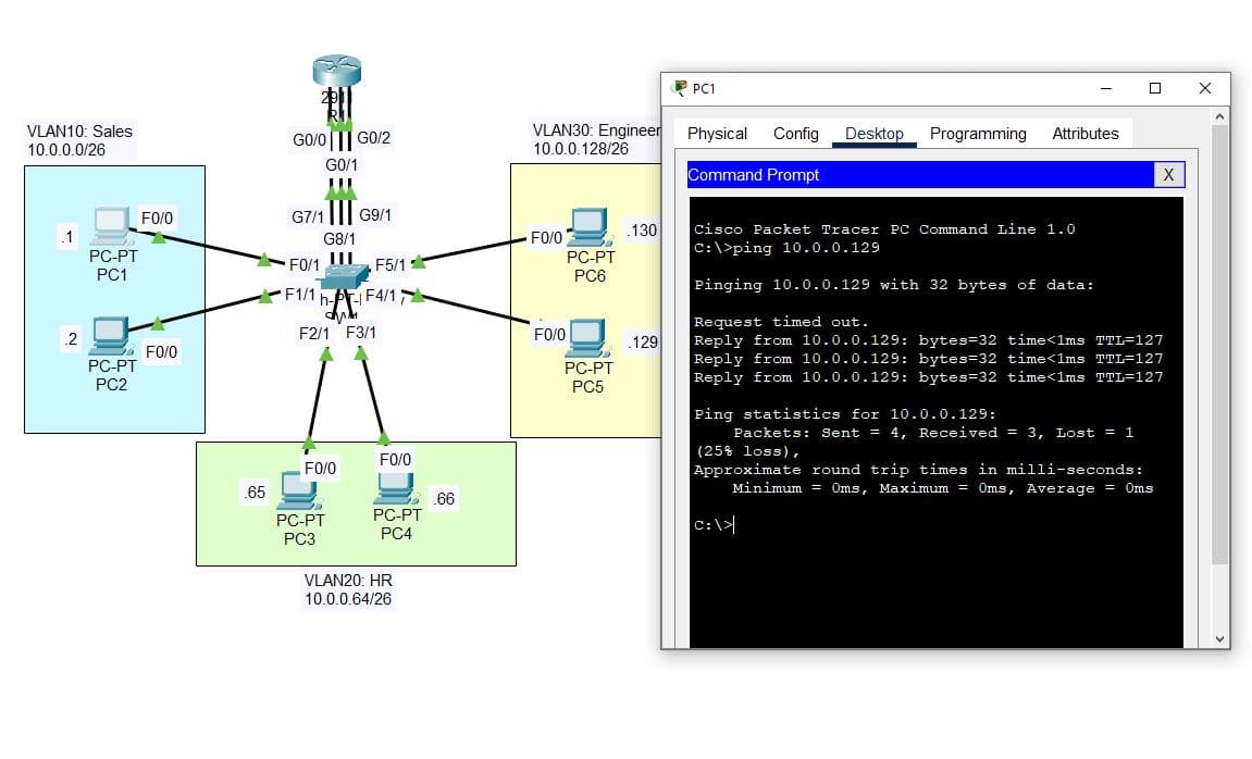
4. Successful Inter-VLAN Connectivity
Now all the links are showing connected and to test inter-vlan connectivity, I ping PC5 in VLAN30 to PC1 in VLAN10 and receive replies.