Multi-VLAN Segmentation with Layer 3 Switch
Overview
Configured a multi-VLAN network using a multilayer switch and trunking, assigning proper subnets and access ports, then enabled inter-VLAN routing via switch virtual interfaces (SVIs).
| Skills Demonstrated |
|---|
| Creating and assigning VLANs for department-based segmentation |
| Calculating and applying subnetting for scalable IP allocation |
| Creating and configuring trunk ports between switches and to the router for VLAN propagation |
| Naming and managing VLANs using best practices |
| Simulating a multi-department structure: Sales (VLAN10), HR (VLAN20), Engineering (VLAN30) |
| Enabling Layer 3 routing via SVIs on a Multilayer Switch |
| Setting native VLAN to VLAN1001 for trunk security |
| Verifying trunk status, VLAN propagation, and ROAS functionality via ping tests |
| Demonstrating inter-VLAN connectivity with ping replies across VLANs on different switches |
| Tools Used |
|---|
| Cisco Packet Tracer |
| Switch CLI |
| Router CLI |
| Straight Through & Crossover Cables |
| PC Static IP Configuration Panel |
| Command Line Utilities (ping, show vlan brief, show interfaces trunk, show ip interfaces brief, ip routing) |
1. Network Topology
I separated 8 PCs into 3 VLANs per department with VLAN20 being extended across a switch:
- VLAN10: Sales
- VLAN20: HR
- VLAN30: Engineering

For each VLAN in this example, I went with a /26 subnet which would give me 62 usable hosts to allot for each department to add new PCs to the subnet in the future:
| VLAN | Department | Network Address | Usable Range | Broadcast Address | Gateway |
|---|---|---|---|---|---|
| VLAN10 | Sales | 10.0.0.0 | 10.0.0.1 - 10.0.0.62 | 10.0.0.63 | 10.0.0.62 |
| VLAN20 | HR | 10.0.0.64 | 10.0.0.65 - 10.0.0.126 | 10.0.0.127 | 10.0.0.126 |
| VLAN30 | Engineering | 10.0.0.128 | 10.0.0.129 - 10.0.0.190 | 10.0.0.191 | 10.0.0.190 |
Since they are different devices, I then connected straight through cables from each PC to their respective switch:
- PC1 F0/0 → Multilayer SW1 G1/0/1 (VLAN10)
- PC2 F0/0 → Multilayer SW1 G1/0/2 (VLAN10)
- PC3 F0/0 → Multilayer SW1 G1/0/3 (VLAN20)
- PC4 F0/0 → Multilayer SW1 G1/0/4 (VLAN20)
- PC5 F0/0 → SW2 F0/1 (VLAN30)
- PC6 F0/0 → SW2 F1/1 (VLAN30)
- PC7 F0/0 → SW2 F2/1 (VLAN20)
- PC8 F0/0 → SW2 F3/1 (VLAN20)

For this lab, since I am using a Layer 3/Multilayer switch for inter-vlan routing I will also connect a straight-through cable from Multilayer SW1 → SW2.
- Multilayer SW1 G1/0/5 → SW2 F4/1 (Trunk - VLAN20, VLAN30)

2. PC Configuration
Then I go into each PC's config settings and set the appropriate IP address and subnet mask based on the /26 subnet:

I then go to each PC and set the default gateway in the config settings to the last usable address of each subnet range. This is necessary for the inter-vlan routing when I set the IP addresses on the router later:

The final IP configurations for the PCs:
| PC | IP Address | Subnet Mask | Gateway |
|---|---|---|---|
| PC1 | 10.0.0.1 | 255.255.255.192 | 10.0.0.62 |
| PC2 | 10.0.0.2 | 255.255.255.192 | 10.0.0.62 |
| PC3 | 10.0.0.65 | 255.255.255.192 | 10.0.0.126 |
| PC4 | 10.0.0.66 | 255.255.255.192 | 10.0.0.126 |
| PC5 | 10.0.0.129 | 255.255.255.192 | 10.0.0.190 |
| PC6 | 10.0.0.130 | 255.255.255.192 | 10.0.0.190 |
| PC7 | 10.0.0.67 | 255.255.255.192 | 10.0.0.126 |
| PC8 | 10.0.0.68 | 255.255.255.192 | 10.0.0.126 |
After setting up the IP address and subnet mask for each PC, I do a quick ping check on PC1.
From PC1, I first ping 10.0.0.2 (PC2) to confirm that I get replies, and then ping 10.0.0.65 (PC3) which is in a different subnet. I do this to confirm that it can't yet reach PC3 since it's in a different subnet. They will be able to ping each other later once I set up the layer 3 switch.

3. Switch Configuration - SW2
First I configure SW2 which is the regular switch. I begin configuring the access ports, and then I configure the trunk port between SW2 and Multilayer SW1.
Before that, I enable an MD5 secret password on the switches for security best practices and save it to startup configuration:
Switch> enable
Switch# conf t
Switch(config)# enable secret [password]
Switch(config)# exit
Switch# write
Then I change the hostname from "Switch" to "SW1" and "SW2" just to make it easier to know which switch is which:
SW1
Switch> enable
Switch# conf t
Switch(config)# hostname SW1
SW1(config)# exit
SW1# write
SW2
Switch> enable
Switch# conf t
Switch(config)# hostname SW2
SW2(config)# exit
SW1# write
Now that I enabled the secret password and changed the hostname, it's time to configure the interfaces to join the VLANs.
First I run "show vlan brief" in the following commands to see the VLAN status of each ports. We can see that the default native VLAN1 and the other defaults of VLAN1002 - 1005 are set and that each port on both switches is currently in VLAN1:
SW1> enable
SW1# show vlan brief
| VLAN | Name | Status | Ports |
|---|---|---|---|
| 1 | default | active | Fa0/1, Fa1/1, Fa2/1, Fa3/1, Fa4/1, Fa5/1, Fa6/1, Gig7/1 |
| 1002 | fddi-default | active | |
| 1003 | token-ring-default | active | |
| 1004 | fddinet-default | active | |
| 1005 | trnet-default | active |
Now, I configure f0/1 and f1/1 to VLAN30 and name VLAN30 "Engineering" by running the following commands:
SW2> enable
SW2# conf t
SW2(config)# int range f0/1,f1/1
SW2(config-if-range)# switchport access vlan 30
SW2(config-if-range)# exit
SW2(config)# vlan 30
SW2(config-vlan)# name Engineering
Next I configure f2/1 and f3/1 on SW2 to VLAN20 and name VLAN20 "HR" by running the following commands:
SW2> enable
SW2# conf t
SW2(config)# int range f2/1,f3/1
SW2(config-if-range)# switchport access vlan 20
SW2(config-if-range)# exit
SW2(config)# vlan 20
SW2(config-vlan)# name HR
Now when running "show vlan brief" on SW2 we can see each port is assigned to the correct VLAN and has the proper name:
| VLAN | Name | Status | Ports |
|---|---|---|---|
| 1 | default | active | Fa4/1, Fa5/1, Fa6/1, Fa7/1, Fa8/1, Fa9/1 |
| 20 | HR | active | Fa2/1, Fa3/1 |
| 30 | Engineering | active | Fa0/1, Fa1/1 |
| 1002 | fddi-default | active | |
| 1003 | token-ring-default | active | |
| 1004 | fddinet-default | active | |
| 1005 | trnet-default | active |
Next, I set up the trunk port on interface F4/1 by running these commands:
SW2> enable
SW2# conf t
SW2(config)# int range f4/1
SW2(config-if)# switchport mode trunk
SW2(config-if)# switchport trunk allowed vlan 20,30
SW2(config-if)# switchport trunk native vlan 1001
Now when I run command "show interface trunk" we can see the configured trunk VLAN setup:
Trunk Port Configuration Summary
| Port | Mode | Encapsulation | Status | Native VLAN |
|---|---|---|---|---|
| Fa4/1 | on | 802.1q | trunking | 1001 |
VLANs Allowed on Trunk
| Port | VLANs Allowed |
|---|---|
| Fa4/1 | 20, 30 |
VLANs Allowed and Active in Management Domain
| Port | VLANs Active |
|---|---|
| Fa4/1 | 20, 30 |
VLANs in STP Forwarding State (Not Pruned)
| Port | VLANs Forwarding |
|---|---|
| Fa4/1 | 30 |
SW2 is now configured so time to move on to configuring the mulitlayer switch (SW1).
3. Multilayer Switch Configuration - SW1
First I set up the access ports of G1/0/1 and G1/0/2 to the VLAN 10 by running the following commands:
SW1> enable
SW1# conf t
SW1(config)# int range g1/0/1, g1/0/2
SW1(config-if-range)# switchport access vlan 10
SW1(config-if-range)# exit
SW1(config)# vlan 10
SW1(config-vlan)# name Sales
Then I set access ports G1/0/3 and G1/0/4 to VLAN 20 by running the following commands:
SW1> enable
SW1# conf t
SW1(config)# int range g1/0/3, g1/0/4
SW1(config-if-range)# switchport access vlan 20
SW1(config-if-range)# exit
SW1(config)# vlan 20
SW1(config-vlan)# name HR
Now when running "show vlan brief" we can see the correctly configured VLANs:
| VLAN | Name | Status | Ports |
|---|---|---|---|
| 1 | default | active | Gig1/0/6, Gig1/0/7, Gig1/0/8, Gig1/0/9, Gig1/0/10, Gig1/0/11, Gig1/0/12, Gig1/0/13, |
| Gig1/0/14, Gig1/0/15, Gig1/0/16, Gig1/0/17, Gig1/0/18, Gig1/0/19, Gig1/0/20, Gig1/0/21, | |||
| Gig1/0/22, Gig1/0/23, Gig1/0/24, Gig1/1/1, Gig1/1/2, Gig1/1/3, Gig1/1/4 | |||
| 10 | Sales | active | Gig1/0/1, Gig1/0/2 |
| 20 | HR | active | Gig1/0/3, Gig1/0/4 |
| 1002 | fddi-default | active | |
| 1003 | token-ring-default | active | |
| 1004 | fddinet-default | active | |
| 1005 | trnet-default | active |
Now I set up the trunk port on G1/0/5 which is connected to SW2 and configure the native VLAN to match SW2:
SW1> enable
SW1# conf t
SW1#(config)# int g1/0/5
SW1#(config-if)# switchport mode trunk
SW1#(config-if)# switchport trunk allowed vlan 10,20,30
SW1#(config-if)# switchport trunk native vlan 1001
SW1(config-if)# exit
SW1(config)# exit vlan 30
Now when running "show interface trunk" we can see the correct trunk VLAN setup:
Trunk Port Configuration Summary
| Port | Mode | Encapsulation | Status | Native VLAN |
|---|---|---|---|---|
| Gig1/0/5 | on | 802.1q | trunking | 1001 |
VLANs Allowed on Trunk
| Port | VLANs Allowed |
|---|---|
| Gig1/0/5 | 10, 20, 30 |
VLANs Allowed and Active in Management Domain
| Port | VLANs Active |
|---|---|
| Gig1/0/5 | 10, 20, 30 |
VLANs in STP Forwarding State (Not Pruned)
| Port | VLANs Forwarding |
|---|---|
| Gig1/0/5 | 10, 20, 30 |
4. Multilayer Switch Configuration - Switch Virtual interfaces
Now that I have all the access and trunk ports set up, it's time to enable "ip routing" and configure the SVI's on Multilayer SW1 to have the appropriate IP address for each subnet:
SW1> enable
SW1# conf t
SW1#(config)# ip routing
SW1#(config)# int vlan 10
SW1#(config-if)# ip address 10.0.0.62 255.255.255.192
SW1#(config-if)# int vlan 20
SW1#(config-if)# ip address 10.0.0.126 255.255.255.192
SW1#(config-if)# int vlan 30
SW1#(config-if)# ip address 10.0.0.190 255.255.255.192
When running "show ip interface brief" I get the following output and we see that the SVI's have been configured and are up/up:
| Interface | IP Address | OK? | Method | Status | Protocol |
|---|---|---|---|---|---|
| GigabitEthernet1/0/1 | unassigned | YES | unset | up | up |
| GigabitEthernet1/0/2 | unassigned | YES | unset | up | up |
| GigabitEthernet1/0/3 | unassigned | YES | unset | up | up |
| GigabitEthernet1/0/4 | unassigned | YES | unset | up | up |
| GigabitEthernet1/0/5 | unassigned | YES | unset | up | up |
| GigabitEthernet1/0/6 | unassigned | YES | unset | down | down |
| GigabitEthernet1/0/7 | unassigned | YES | unset | down | down |
| GigabitEthernet1/0/8 | unassigned | YES | unset | down | down |
| GigabitEthernet1/0/9 | unassigned | YES | unset | down | down |
| GigabitEthernet1/0/10 | unassigned | YES | unset | down | down |
| GigabitEthernet1/0/11 | unassigned | YES | unset | down | down |
| GigabitEthernet1/0/12 | unassigned | YES | unset | down | down |
| GigabitEthernet1/0/13 | unassigned | YES | unset | down | down |
| GigabitEthernet1/0/14 | unassigned | YES | unset | down | down |
| GigabitEthernet1/0/15 | unassigned | YES | unset | down | down |
| GigabitEthernet1/0/16 | unassigned | YES | unset | down | down |
| GigabitEthernet1/0/17 | unassigned | YES | unset | down | down |
| GigabitEthernet1/0/18 | unassigned | YES | unset | down | down |
| GigabitEthernet1/0/19 | unassigned | YES | unset | down | down |
| GigabitEthernet1/0/20 | unassigned | YES | unset | down | down |
| GigabitEthernet1/0/21 | unassigned | YES | unset | down | down |
| GigabitEthernet1/0/22 | unassigned | YES | unset | down | down |
| GigabitEthernet1/0/23 | unassigned | YES | unset | down | down |
| GigabitEthernet1/0/24 | unassigned | YES | unset | down | down |
| GigabitEthernet1/1/1 | unassigned | YES | unset | down | down |
| GigabitEthernet1/1/2 | unassigned | YES | unset | down | down |
| GigabitEthernet1/1/3 | unassigned | YES | unset | down | down |
| GigabitEthernet1/1/4 | unassigned | YES | unset | down | down |
| Vlan1 | unassigned | YES | unset | administratively down | down |
| Vlan10 | 10.0.0.62 | YES | manual | up | up |
| Vlan20 | 10.0.0.126 | YES | manual | up | up |
| Vlan30 | 10.0.0.190 | YES | manual | up | up |
And when running "show ip route" we see routes:
     10.0.0.0/26 is subnetted, 3 subnets
C       10.0.0.0 is directly connected, Vlan10
C       10.0.0.64 is directly connected, Vlan20
C       10.0.0.128 is directly connected, Vlan30
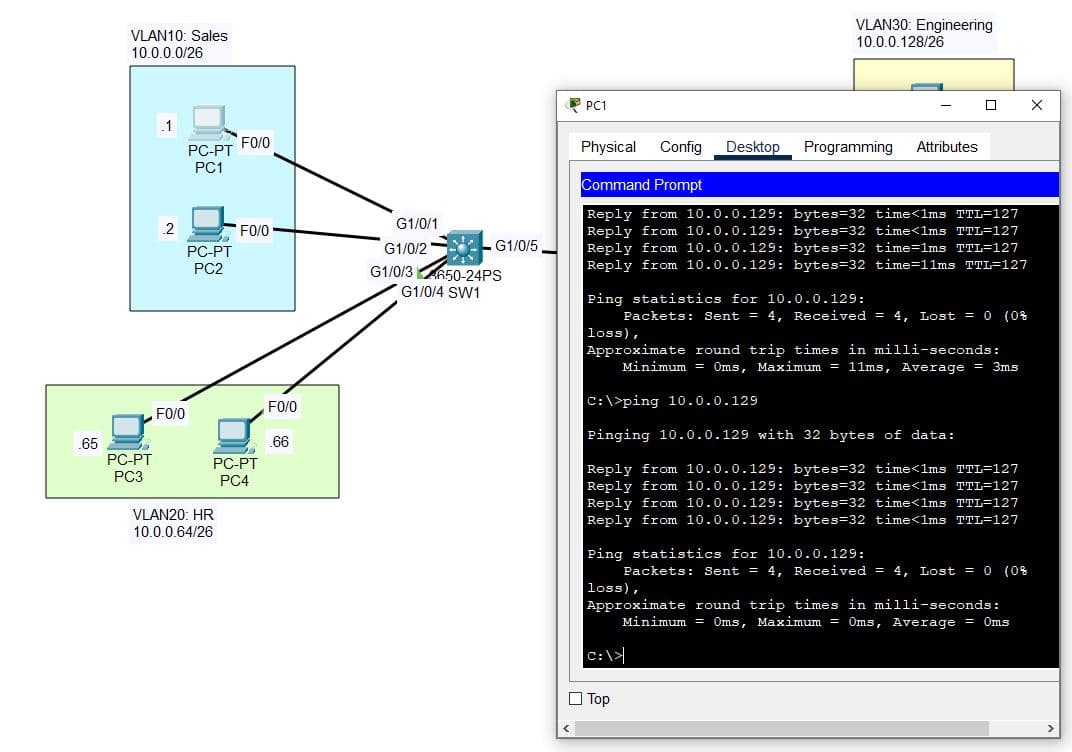
5. Successful Connection
To test inter-vlan connectivity, I ping PC1 to PC5, and we receive successful replies letting us know the connection is successful: